
Capability
Injection molds and tooling
Tool design, build, and sampling. The tool type follows the part and the volume, so quotes state which configuration is proposed and why.
How this works
A mold is a precision assembly, not a single block. Two halves close on a parting line to form the cavity; a feed system delivers melt; cooling channels pull heat out; and an ejection system pushes the part off the core once it has shrunk onto it.
Every decision below is made before steel is cut, and the tool layout drawing is the last cheap moment to change any of them. We ask you to approve that drawing precisely because changes after it are expensive.
A conventional two-plate tool. Melt enters through the sprue, the part forms between the cavity plate and the core plate, and the mold opens on a single parting line. The ejector plates travel forward on opening to push the part off the core. Cooling lines run through both halves close to the molding surface.
Tool types
| Configuration | How it works | When it is right |
|---|---|---|
| Two plate | The simplest tool. Cavity and core separate on one parting line, with the runner in the same plane as the part. | Most parts. Lowest cost and simplest maintenance. The runner stays attached and is trimmed off. |
| Three plate | A second parting line separates the runner from the part automatically, allowing gates in the center of a part face. | Parts needing a center gate, or automatic runner separation without a hot runner. |
| Hot runner | A heated manifold keeps the feed system molten, so no runner solidifies and no scrap is produced. | High volume, expensive resins, or where runner regrind is unacceptable. Higher tool cost and maintenance. |
| Multi-cavity | Several identical cavities filled from one shot. | High volume where unit cost dominates. Flow balance across cavities is the engineering problem. |
| Family tool | Different parts of one assembly in a single tool. | Assemblies molded in the same material and color. You cannot run parts in different ratios. |
| Stack tool | Two or more parting levels stacked, doubling output per shot. Clamp force rises only modestly, because the projected areas sit behind one another rather than side by side. | Very high volume, thin-walled parts such as lids and containers. |
The trade-off between the first two is set out in two-plate vs three-plate mold. Whether a hot runner pays for itself on your volume and resin is worked through in hot runner vs cold runner mold. How cold and hot runners are laid out and balanced is covered in types of runner in an injection mold, and every plate, pin and bushing named on this page is explained in injection mold components explained.
Tool steels and life
Tool material is chosen against expected cycles, resin abrasiveness, and required finish. Glass-filled resins are abrasive and wear soft tools quickly, which is why the resin decision changes the tooling decision.
| Material | Typical designed life | Notes |
|---|---|---|
| Aluminum (7075, QC-10) | Hundreds to a few thousand cycles | Fast to cut and cheap. Excellent thermal conductivity shortens cycles. Limited texture options. |
| P20 pre-hardened steel | 300,000 to 500,000 cycles | The general-purpose production standard. Machines in the pre-hardened state, so no post-hardening distortion. |
| H13 hardened | 1,000,000 cycles on glass-filled resin; 2,000,000 or more unfilled | Higher wear and heat resistance. Used for abrasive filled resins and high-volume programs. |
| 420 stainless | High, with corrosion resistance | For corrosive resins such as PVC, and for medical tools requiring polished, corrosion-free surfaces. |
| S7 shock-resisting | Hundreds of thousands of cycles | Where a large single-cavity tool takes impact on clamp or ejection. Tougher than H13 at the cost of some wear resistance. |
| Beryllium-free copper alloys (Moldmax HH, Ampco 940) | Insert use | Used as cooling inserts in hot spots rather than as whole tools. Beryllium-free grades are chosen because machining BeCu produces a toxic dust. |
Choosing steel from the resin
Cycle count sets the floor, but the resin often overrides it. An abrasive glass or mineral filled grade cuts tool life on P20 by a large factor, so H13 is specified even at moderate volume. PVC and some flame-retardant packages release acidic gas as they process and pit ordinary tool steel, so 420 stainless is used for the cavity and core regardless of volume. Resins that must be run dry, PBT and PA among them, are corrosive when they are not, which is another argument for stainless on a tool that will sit between orders. Where the part is cosmetic and will be polished to a mirror, the steel has to take and hold that polish, which again points at 420 or a high-hardness pre-hardened grade rather than aluminum. See our surface finish guide for how the SPI grades map to steel choice.
Gating
The gate is where melt enters the cavity. It sets fill pattern, weld line position, packing efficiency, and the cosmetic mark left on the part. It is the single most consequential tool decision after the parting line.
| Gate type | Characteristics |
|---|---|
| Edge gate | Simplest and most common. Gates onto the part edge on the parting line. Leaves a small tab requiring trim. |
| Submarine (tunnel) gate | Shears off automatically on ejection. Small vestige, good for automated production. |
| Hot tip / direct | Gates directly onto the part face from a hot runner nozzle. No runner, small round vestige. |
| Fan gate | Widens toward the cavity to spread flow evenly. Reduces warp on wide, thin parts. |
| Diaphragm gate | Feeds a cylindrical part around its full circumference for concentricity. Requires machining off. |
Gates are where the melt enters the cavity. The choice sets the vestige left on the part, whether degating is manual or automatic, and how the part fills. It is a tooling decision with a permanent effect on unit cost.
Cooling and cycle time
Cooling is usually the largest single component of cycle time, and cycle time is what you pay for on every part for the life of the tool. Cooling design is therefore an economic decision, not just an engineering one.
- Channels are placed to hold uniform tool surface temperature, since uneven cooling causes warp.
- Cores are harder to cool than cavities, because heat has nowhere to go. Bubblers, baffles, and conductive inserts address this.
- Thick sections dictate cooling time regardless of the rest of the part, which is another reason uniform walls matter.
- Conformal cooling, where channels follow the part surface, can cut cycle time substantially on difficult geometry.
Drilled straight lines are cheap but sit at varying distances from the molding surface, so the part cools unevenly and warps. A conformal circuit follows the contour, holds a constant distance and takes time out of the cycle. It costs more to make.
From design to first article
- Design for manufacture review of your part model, returned before any tooling is committed
- Tool layout drawing: parting line, cavitation, gate and runner, ejection, cooling, actions
- Your approval of that layout, which is the last inexpensive point to change the design
- Steel ordered, rough machined, then EDM, polishing, texturing, and fitting
- T0 first shots, dimensional measurement against your drawing, and a sample report
- Tool adjustment where required, then T1 and approval for production
Cavities are cut steel safe wherever a critical dimension is in question. Removing steel to grow a part dimension is routine; adding it back means welding or a new insert.
How the T0 and T1 samples are measured and what the first article report contains is on the quality and inspection page. The week-by-week timeline from CAD to approved samples, including where the 4 to 8 weeks goes, is in the injection molding lead time guide.
Ownership, storage, and transfer
Tool ownership is the clause buyers read first, and it should be in writing before a purchase order, not discovered later.
- Who owns the tool once it is paid for, and what documentation proves it
- Where the tool is stored between runs and who insures it
- Maintenance schedule and who bears the cost of routine servicing
- Conditions and notice period for transferring a tool to another manufacturer
- Whether an existing tool built elsewhere can be received, inspected, and run
A tool paid for in full is your property from final payment. We hold custody while we run the parts, maintain it as part of production, and release it on written request once sums due are paid.
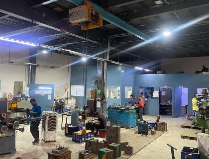
Ownership is one of several questions worth putting to any manufacturer before a purchase order; see our checklist for choosing an injection mold manufacturer for the rest. How we build, store and maintain tools in Delhi is set out on our mould manufacturing company in India page.
Questions
Frequently asked
What buyers ask before committing to a tool. Each answer comes from the sections above.
Ask an engineerWhich type of injection mold do I need?
The tool type follows the part and the volume. A two-plate tool is the simplest and suits most parts; a three-plate tool separates the runner automatically; hot runner tools remove the runner altogether for high volumes and cosmetic gates; family and multi-cavity tools trade higher tool cost for lower part cost. Trumould quotes state which configuration is proposed and why.
Aluminum or steel: how long does each mold last?
Tool material is chosen against expected cycles, resin abrasiveness and required finish. Aluminum tools (7075, QC-10) are fast to cut and cheap and are designed for hundreds to a few thousand cycles; P20 pre-hardened and H13 hardened steels take the volume up to a designed life of 2,000,000 cycles by steel selection. Glass-filled resins are abrasive and wear soft tools quickly, so the resin choice changes the tooling choice.
Why does the gate location matter so much?
The gate sets the fill pattern, the weld line positions, the packing efficiency and the cosmetic mark left on the part. It is the single most consequential tool decision after the parting line, which is why it is fixed on the tool layout drawing you approve before steel is cut.
Who owns the mold once it is paid for?
You do, and it should be in writing before a purchase order: who owns the tool and what documentation proves it, where it is stored between runs and who insures it, the maintenance schedule and who bears routine servicing, and the conditions under which it is transferred. In practice the tool stays on Trumould's floor while in production so it can be run, maintained and corrected without shipping delays, and it leaves whenever you ask.
What happens between sending CAD and receiving first samples?
Design-for-manufacture review of your model, returned before tooling is committed; a tool layout drawing covering parting line, cavitation, gate and runner, ejection, cooling and actions; your approval of that layout, the last inexpensive point to change anything; steel ordered and machined, EDM, polishing and texturing; then first article (T0/T1) sampling and measurement against your drawing.
Also available
Other capabilities
Injection molding
Production molding runs from a tool you already own or one we build for you. Quotes cover the part, the tool, and the lead time separately so you can see what you are paying for.
CNC machining
Milling and turning from metal and plastic stock, for prototypes through to production quantities.
3D printing
Additive parts for fit checks, prototypes, and low volume production, where tooling would not pay for itself.
Let’s get started on your part
Send your CAD files and target volumes. We come back with a price, a lead time, and any design notes that would reduce either.