
Capability
Custom plastic injection molding services
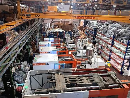
Trumould molds custom plastic parts in its own Delhi plant, from a tool you already own or one our toolroom builds for you. An engineer quotes the part, the tool, and the lead time as separate numbers within 24 to 48 hours, so you can see what you are paying for.
How this works
Injection molding forces molten polymer into a closed steel or aluminum tool under pressure, holds it while it cools, then ejects the part. The tool is the capital cost; once it exists, each part costs very little. That single fact governs every decision on this page.
A quote from us separates three numbers: the tool, the per-part price at the volumes you name, and the lead time to first article. Bundling them hides which one you are actually paying for.
For the fuller walkthrough, step by step, with common defects and their causes, see how injection molding works.
Pellets melt in the barrel as the screw turns and shears them. The screw then moves forward as a plunger and pushes the shot through the nozzle, down the sprue and into the cavity. Clamp force holds the two halves shut against injection pressure. Once the part is rigid the mold opens on the parting line and ejector pins push it off the core.
When molding is the right process
Molding pays back when the tool cost divides across enough parts to beat the per-part cost of machining or printing. The crossover depends on part size and complexity, but the shape of the decision is consistent.
- Under roughly 100 parts, printing or machining is almost always cheaper, because no tool has to be paid for.
- Between roughly 100 and 1,000 parts, a prototype aluminum tool often wins, since it costs a fraction of production steel and runs the volumes needed.
- Above roughly 1,000 parts a year, production tooling usually wins outright, and the gap widens with every part.
- Volume is not the only trigger. Molding is also the right answer when you need a specific resin, a cosmetic finish, living hinges, or overmolded assemblies that no other process produces.
Tooling options
The tool type follows the part and the volume. A tool sized for 500 parts and a tool sized for 500,000 are different objects with different steels, different cooling, and a tenfold cost difference.
| Tool type | Typical use | Trade-off |
|---|---|---|
| Prototype aluminum | Bridge volumes, design validation, 100 to 5,000 parts | Lowest cost and fastest to cut. Softer, so tool life is limited and textures are restricted. |
| Production steel, single cavity | 1,000 to 100,000 parts a year | Long tool life, good finish. One part per cycle, so cycle time drives unit cost. |
| Multi-cavity | High volume where unit cost dominates | Several parts per shot cuts unit cost sharply. Higher tool cost and cavity-to-cavity variation must be managed. |
| Family tool | Several different parts of one assembly | One tool instead of several. Flow balancing is harder and you cannot run parts in different ratios. |
| Hot runner | High volume, no runner scrap | Eliminates runner waste and shortens cycles. Higher tool cost and more maintenance. |
| Insert molding | Metal inserts, threads, terminals, magnets | One shot. Inserts are loaded into the tool before it closes, so cycle time rises with the loading operation but tool cost stays close to a standard tool. |
| Overmolding | Soft-touch grips, seals, hard-on-hard multi-material parts | Two shots, either on a two-shot press with a rotating platen or by robot transfer between tools. Tool cost roughly doubles. Below tens of thousands a year, insert overmolding on two simpler tools usually wins on total cost. Full comparison: overmolding vs insert molding. |
A single cavity aluminum tool is cut in a fraction of the time and is the right answer while a design is still moving. A multi-cavity hardened tool costs more than the cavity count suggests, because every cavity has to be balanced and matched, but it divides the cycle time across four parts and it will outlive the program.
Materials
Resin choice sets the mechanical performance, the shrinkage, the cycle time, and often the tolerance you can hold. Specify the grade, not just the family: PA66 unfilled and PA66-GF30 shrink differently and cannot share a tool without a change.
Commodity resins
| Material | Chosen for |
|---|---|
| ABS | General purpose housings and enclosures. Easy to mold, paints and plates well. Degrades under UV, so outdoors it is replaced by ASA, or by PC-ABS with a UV stabilizer package as used on automotive exteriors. |
| PP | Living hinges, chemical resistance, low cost. High shrinkage, so tolerances are looser. |
| PE (HDPE, LDPE) | Containers, chemical resistance, low friction. Difficult to bond or paint. |
| PS and HIPS | Low cost rigid parts and packaging. Brittle, poor chemical resistance. |
| PMMA (acrylic) | Optical clarity, lenses, light pipes. Brittle and notch sensitive. |
Engineering resins
| Material | Chosen for |
|---|---|
| PC | Impact strength and clarity. Notch sensitive, so avoid sharp internal corners. Needs drying before molding. |
| PC-ABS | Balance of PC toughness and ABS processability. Common for enclosures that must survive a drop. |
| PA6 and PA66 | Strength, wear, and temperature resistance. Absorbs moisture, which moves dimensions after molding. |
| PA-GF30 | Glass filled nylon for structural parts. Much stiffer, but anisotropic shrinkage and abrasive to tools. |
| POM (acetal) | Low friction and dimensional stability for gears and bearings. Narrow processing window. |
| PBT and PBT-GF | Electrical parts, connectors. Good dielectric properties and dimensional stability. See electronics injection molding for connector and enclosure parts. |
| TPE and TPU | Overmolded grips, seals, and flexible parts. Bond compatibility with the substrate must be checked. See TPE vs TPU for softness against abrasion. |
High-performance resins
| Material | Chosen for |
|---|---|
| PEEK | Continuous high temperature and chemical resistance. Cost per kilo decides most inquiries. |
| PEI (Ultem) | High temperature with inherent UL94 V-0 flame retardance and no additives. |
| PPS | Chemical and temperature resistance for under-bonnet and fluid-handling parts. |
| PSU | Repeated steam autoclaving, medical and lab equipment. |
Reading a grade code
A resin is specified by grade, not by family, and the suffix carries the information that decides whether the part works. GF or GB with a number is glass fiber or bead content by weight, so PA66-GF30 is thirty percent glass. MD is mineral filler, TD talc. V0 and HB are UL 94 flammability ratings, V-0 being the self-extinguishing one that mains-powered enclosures usually need. FR means a flame retardant package is present, which usually costs some impact strength. UV is a light stabilizer package. HI is high impact, MFI or a melt flow number tells you how easily it fills a thin wall.
Two grades in the same family shrink differently once a filler is involved, so a grade change after the tool is cut is a tool change. Nominate the grade on the drawing, not the family.
Regrind
Runners and rejected parts can be granulated and blended back into virgin material. We keep regrind to a modest fraction and state the percentage on the order, because each pass through the barrel shortens the polymer chains and costs impact strength. Where a part is safety-critical, medical, or food-contact, we run virgin material only. Tell us at inquiry stage if regrind is prohibited, because it affects the piece price.
Tolerances
Molded plastic tolerance is governed by DIN 16742, which sets tolerance groups by material and dimension rather than a single number. Shrinkage varies by resin, by fill, and by direction of flow, so a tolerance that is routine in POM may be impossible in PP on the same geometry.
- Low-shrink, unfilled resins such as ABS, PC, and POM hold the tightest tolerances.
- High-shrink resins such as PP and PE, and filled grades with anisotropic shrinkage, hold the loosest.
- Dimensions across the parting line are always looser than dimensions within one half of the tool, because they include the clamp.
- Tolerance stacks with part size. A percentage-based deviation on a 300 mm part is a large absolute number.
- Call out only the features that carry a fit or a function. Applying a tight block to a whole drawing raises price without improving the part.
- For anything critical, tool steel can be cut "steel safe" and adjusted after first samples. It is far cheaper to remove steel than to add it.
| Material | DIN 16742 group | Tolerance at 100 mm |
|---|---|---|
| POM | TG5 | ±0.20 mm |
| PC | TG5 | ±0.20 mm |
| ABS | TG6 | ±0.28 mm |
| PA66 | TG7 | ±0.36 mm |
| PA66-GF30 | TG7 to TG8 | ±0.36 to ±0.52 mm |
| PP | TG8 | ±0.52 mm |
Use this to size a drawing before you send it. Anything tighter than the group figure is achievable on individual features, but it is a cavity-design decision and it is priced as one, so nominate the few dimensions that matter rather than tightening the whole part. For the full picture, including why shrinkage percentage is not the same thing as tolerance and how to call out a drawing so it prices correctly, see our injection molding tolerances guide.
Surface finishes
The tool surface is transferred to every part, so finish is a tooling decision made before steel is cut, not a post-process. The SPI standard is the common reference; VDI 3400 and Mold-Tech are used for textures.
| Finish | Description | Typical use |
|---|---|---|
| SPI A1 to A3 | Diamond buffed, high gloss | Lenses, light pipes, cosmetic gloss surfaces |
| SPI B1 to B3 | Paper polished, semi-gloss | General cosmetic surfaces, painted parts |
| SPI C1 to C3 | Stone finished, matte | Non-cosmetic surfaces, internal parts |
| SPI D1 to D3 | Bead or grit blasted, textured matte | Hides sink and flow marks, grip surfaces |
| VDI 3400 | EDM textures on a numbered scale | Repeatable engineering textures |
| Mold-Tech | Etched pattern textures | Leather grains, geometric patterns, consumer housings |
Higher gloss requires more draft, not less. A polished vertical wall will drag on ejection where a matte one would release. Textured surfaces need roughly one additional degree of draft per 0.025 mm of texture depth.
Finish is specified as a roughness average, and each grade is a separate operation rather than a setting on the previous one. A cosmetic or sealing surface earns a tight number. Everywhere else, the finish left by the process that made the part is usually adequate and free. Our injection mold surface finish guide covers the SPI A to D grades and how to call one out on a drawing.
Design rules that decide cost
- Keep wall thickness uniform. Typically 1.0 to 3.0 mm for engineering resins, thinner for polyolefins, packaging in PP runs to 0.5 mm, and up to 4 or 5 mm on structural glass-filled parts. Variation above about 25 percent causes sink, warp, and voids.
- Add draft to every face parallel to the direction of pull. One degree is a working minimum on smooth surfaces, three or more on textures.
- Radius internal corners at roughly 0.5 times the wall thickness. Sharp corners concentrate stress and restrict flow.
- Size ribs at 40 to 60 percent of the adjoining wall where the opposite face is cosmetic, and up to 70 percent where it is not. Thicker ribs pull sink marks on the visible face opposite.
- Support bosses with ribs or gussets rather than thickening them. A thick boss is a sink mark waiting to happen.
- Avoid undercuts where you can. Each one needs a side action or lifter, which adds tool cost and cycle time.
- Place gates on the thickest section, feeding thick to thin, and away from cosmetic faces. Gate position determines where weld lines land.
- Plan ejector pin locations early. They leave witness marks, and those marks have to go somewhere non-critical.
Secondary operations
- Pad printing and screen printing for logos and legends
- Laser marking and engraving, including date and lot codes
- Painting, including soft-touch and EMI shielding coatings
- Ultrasonic welding and heat staking for assemblies
- Heat-set and ultrasonic threaded insert installation
- In-mold labelling and in-mold decoration
- Assembly, kitting, and packaging to your specification
What drives lead time
Tooling dominates the schedule on any new part. Production runs afterwards are short by comparison. The full timeline, stage by stage, with freight to Indian cities and the United States, is on the injection molding lead time page.
- Design for manufacture review and quotation, before any steel is committed
- Tool design and your approval of the layout, which is the last cheap point to change anything
- Tool build: rough machining, EDM, polishing, and fitting
- First article sampling (T0), measurement, and any tool adjustment
- Approval and production release
Lead times are quoted per part rather than averaged: tool build, first article, and production release are three separate dates on the quotation.
A typical unfilled thermoplastic cycle. Injection itself is a second or two. Cooling is the majority of the cycle and is governed by the thickest section of the part, which is why wall thickness drives piece price more than any other geometric choice.
Quality and documentation
What ships with the parts matters as much as the parts on a regulated or automotive program. Documentation is agreed before the order, not requested afterwards.
- First article inspection report against your drawing
- Dimensional report on sampled parts from the production run
- Material certificates traceable to resin grade and lot
- Process capability study (Cpk) on nominated critical dimensions
- PPAP submission where the program requires it
Certificates and their scope are supplied with the quotation for the program they apply to. See the full quality and certification page, and our guide to avoiding common molding defects. Tools are built and maintained by our own mould manufacturing team, and export volumes are covered on the bulk injection molding exporter page.
Questions
Frequently asked
The questions buyers ask before their first molding order. Each answer comes from the sections above.
Ask an engineerAt what quantity does injection molding become cheaper than machining or 3D printing?
Molding pays back when the tool cost divides across enough parts. Under roughly 100 parts, printing or machining is almost always cheaper because no tool has to be paid for. Between roughly 100 and 1,000 parts a prototype aluminum tool often wins. Above that, production steel tooling and multi-cavity layouts bring the per-part price down further. The exact crossover depends on part size and complexity, which is why a Trumould quote states the tool, the per-part price at your volumes, and the lead time as three separate numbers.
What tolerances can molded plastic parts hold?
Molded plastic tolerance follows DIN 16742, which sets tolerance groups by material and dimension rather than one number. Low-shrink, unfilled resins such as ABS, PC and POM hold the tightest tolerances; high-shrink resins such as PP and PE, and glass-filled grades, hold looser ones. Tell us which dimensions actually matter and we will confirm what the chosen resin and tool can hold before steel is cut.
Which surface finishes are available on molded parts?
Finish is a tooling decision made before steel is cut, because the tool surface transfers to every part. Trumould works to the SPI scale (A1 to A3 diamond-buffed high gloss, B1 to B3 semi-gloss, C1 to C3 matte, D1 to D3 dull) and to VDI 3400 and Mold-Tech references for textures.
What documentation ships with molded parts?
Agreed before the order, not requested afterwards: first article inspection report against your drawing, dimensional report on sampled production parts, material certificates traceable to resin grade and lot, process capability study (Cpk) on nominated critical dimensions, and PPAP submission where the program requires it.
What secondary operations can Trumould do on molded parts?
Pad and screen printing, laser marking including date and lot codes, painting including soft-touch and EMI shielding coatings, ultrasonic welding and heat staking, heat-set and ultrasonic threaded insert installation, in-mold labelling and decoration, and assembly, kitting and packaging to your specification.
Where are Trumould’s injection molded parts made?
In Trumould’s own plant on GT Karnal Road, Delhi, where the tooling shop and the press floor share one site. Parts ship by road to buyers across India, and by air or sea to the United States, European Union, United Kingdom and GCC. Quotes come from an engineer at the plant within 24 to 48 hours. More on the plant: injection molding company in Delhi.
What drives the lead time on a new molded part?
Tooling dominates the schedule; production runs afterwards are short by comparison. The sequence is design-for-manufacture review and quotation, tool design and your approval of the layout, tool build (rough machining, EDM, polishing, fitting), first article sampling and measurement, then approval and production release.
Also available
Other capabilities
Injection molds and tooling
Tool design, build, and sampling. The tool type follows the part and the volume, so quotes state which configuration is proposed and why.
CNC machining
Milling and turning from metal and plastic stock, for prototypes through to production quantities.
3D printing
Additive parts for fit checks, prototypes, and low volume production, where tooling would not pay for itself.
Let’s get started on your part
Send your CAD files and target volumes. We come back with a price, a lead time, and any design notes that would reduce either.