
Capability
CNC machining
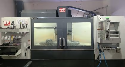
Milling and turning from metal and plastic stock, for prototypes through to production quantities.
How this works
Machining removes material from solid stock with a rotating cutter, or rotates the stock against a fixed tool in the case of turning. Because it is subtractive, it needs no tooling investment, which is what makes it the default for low volumes and for anything that must be made from real engineering material.
Cost is driven by time on the machine and the number of setups, not by part complexity in the abstract. A complicated part cut in one setup can be cheaper than a simple part that has to be flipped four times.
For plastic parts specifically, see injection molding vs CNC machining for where the volume crossover against tooling actually sits.
Milling moves the work against a spinning cutter. Turning spins the work against a fixed tool. Rotationally symmetric features belong on a lathe, prismatic features on a mill, and a part needing both will cost two setups.
Processes
| Process | What it does | Typical use |
|---|---|---|
| 3-axis milling | Cutter moves in X, Y, Z against a fixed part. | Prismatic parts, plates, housings. Cheapest per hour. Each new face is a new setup. |
| 4-axis milling | Adds a rotary axis, so the part can be indexed or cut while rotating. | Parts with features on several faces, cylindrical features, fewer setups than 3-axis. |
| 5-axis milling | Two rotary axes allow the cutter to approach from almost any angle. | Complex contoured parts, impellers, undercuts. Fewer setups means better tolerance between features. |
| Turning | Part rotates against a fixed tool. | Shafts, pins, bushings, anything cylindrical. Very fast for round parts. |
| Mill-turn | Turning with live tooling for milled features. | Round parts with flats, cross-holes, or slots, completed in one setup. |
| Wire and sinker EDM | Material removed by electrical discharge rather than cutting. | Sharp internal corners, hardened steel, features no cutter can reach. |
Materials
Machining works in real engineering material, which is often the whole reason for choosing it. Specify the alloy and temper: "aluminum" is not a specification, 6061-T6 is.
| Material | Chosen for |
|---|---|
| Aluminum 6061-T6 | General purpose. Machines fast, anodises well, good strength to weight. The default prototype metal. |
| Aluminum 7075-T6 | Higher strength for structural parts. Not weldable and less corrosion resistant than 6061. |
| Aluminum 5052 | Corrosion resistance and formability. Common where parts are also formed or welded. 6063 is the common extrusion alloy in the US and machines similarly, though it is softer and finishes less crisply. |
| Stainless 304 | General corrosion resistance at moderate cost. Not corrosion proof. Weighed against 6061 in 6061 aluminum vs 304 stainless steel. |
| Stainless 316 / 316L | Chloride and marine resistance. Specify 316L where the part will be welded. |
| Stainless 17-4PH | High strength with corrosion resistance, heat treatable to a range of conditions. |
| Steel 1018 | Low cost, welds and machines easily. Needs case hardening for wear. |
| Steel 4140 | Strength and wear when quenched and tempered. State the required condition. |
| Brass C360 | The machinability benchmark. Leaded, so check RoHS and potable water limits. |
| Titanium Ti-6Al-4V | Strength to weight and corrosion resistance. Slow and costly to cut. |
| Delrin (POM) | Low friction and dimensional stability for gears and bearings. |
| PEEK, PTFE, Ultem | Temperature, chemical resistance, and electrical insulation where metal will not do. |
Tolerances
If a drawing carries no tolerance callout, a general tolerance applies, normally taken from ISO 2768. The class you specify, fine through very coarse, sets the permitted deviation and it widens as nominal dimensions grow.
- Put a general tolerance block on the drawing so undimensioned features are unambiguous.
- Tighten individual features only where they carry a fit or a function. A tight block applied to a whole drawing multiplies inspection cost without improving the part.
- Geometric tolerance, such as flatness, position, and concentricity, is often what actually matters, and is cheaper than over-tightening every linear dimension.
- State the datum scheme. Position tolerance without datums cannot be measured.
- A tolerance tighter than the measuring equipment can resolve cannot be verified, and becomes an argument after delivery.
- Plastics move with temperature and humidity. A tolerance routine in aluminum may be unachievable in nylon.
Surface finishes
| Finish | Description |
|---|---|
| As-machined | Standard finish with visible tool marks. The default and the cheapest. |
| Bead blasted | Uniform matte texture that removes tool marks. Common before anodising. |
| Anodised, Type II | Corrosion resistance and color on aluminum. Adds a few microns per surface. |
| Anodised, Type III (hard) | Thick, wear-resistant layer for functional surfaces. Adds meaningful thickness. |
| Powder coating | Durable colored finish on steel and aluminum. Thick, so mask critical features. |
| Electropolishing | Smooths and passivates stainless. Common on medical and food-contact parts. |
| Black oxide | Mild corrosion resistance on steel with minimal dimensional change. |
| Passivation | Removes free iron from stainless to restore corrosion resistance after machining. |
Process capability
Where a buyer needs capability rather than a single measurement, we run a capability study on the nominated dimensions and report Cpk against the drawing limits. Cpk 1.33 is the usual target for a general production feature and 1.67 where the feature is safety-related. Say at inquiry stage which dimensions need it, because it changes how many parts are measured and therefore the price.
What a STEP file cannot tell us
A STEP file carries geometry and nothing else: no tolerance, no datum scheme, no surface finish, no material. Send a drawing with it, even a single-sheet PDF, and mark only the dimensions that carry a fit or a function. Everything unmarked is made to the general tolerance block, which is the cheapest way to buy the features that do not matter.
Specify the finish before final dimensions are fixed. Anodising and plating add thickness, and a tight hole that was in tolerance as-machined can be out of tolerance after coating.
Setups, not features, drive the price of a machined part. Every flip means re-clamping, re-indicating and a new datum, and any dimension that spans two setups inherits the error of both. A part designed so the critical features can be reached without turning it over is cheaper and more accurate at the same time.
Design rules that decide cost
- Internal corners carry the radius of the cutter. Design them with a generous radius, since a larger tool is stiffer and faster.
- Keep pocket depth to roughly four times the tool diameter. Deeper needs long thin tools that chatter.
- Every face requiring a different approach direction is another setup, and every setup adds cost and stacks tolerance.
- Use standard drill sizes wherever the fit allows. Arbitrary reamed or bored diameters cost more.
- Keep threads short. A thread deeper than about one and a half times its diameter adds no strength.
- Avoid thin walls and tall unsupported features. They vibrate under the cutter, spoiling finish and tolerance.
- Undercuts need a special tool or a second setup. Both cost money.
A rotating cutter cannot produce a sharp internal corner. Every internal corner in a machined pocket carries at least the cutter radius. Specifying a radius slightly larger than the cutter lets the tool cut through the corner rather than pivot in it, which is faster and leaves a better finish.
Inspection and documentation
- First article inspection report against your drawing before a full run
- Dimensional report with measured values on nominated features
- Material certificates traceable to grade and heat lot
- CMM reporting for geometric tolerance and datum-referenced features
- Certificate of conformity shipped with parts
Inspection is by CMM for dimensional reports and by calibrated hand metrology in process. The equipment list and calibration status for your program are supplied with the quotation.
Questions
Frequently asked
What buyers ask before a machining order. Each answer comes from the sections above.
Ask an engineerWhen is CNC machining the right process instead of molding or printing?
Machining is subtractive, so it needs no tooling investment, which makes it the default for low volumes and for anything that must be made from real engineering material such as 6061-T6 and 7075-T6 aluminum, 304 and 316L stainless, 4140 steel, brass, titanium, or engineering plastics such as POM and PEEK. Cost is driven by machine time and setups, not by a tool that has to be paid off.
What tolerances apply if my drawing does not state one?
A general tolerance applies, normally taken from ISO 2768. The class you specify, fine through very coarse, sets the permitted deviation and it widens as nominal dimensions grow. Trumould holds ±0.05 mm as standard on 3-axis work and ISO 2768-f on uncalled dimensions. Put a general tolerance block on the drawing and tighten only the individual features that need it; every tightened tolerance costs inspection time.
Which machining processes does Trumould offer?
3-axis milling for prismatic parts, plates and housings; 4-axis milling for features on several faces and cylindrical features; 5-axis milling for complex contoured parts in fewer setups; and CNC turning for shafts, bushes and any part that is round about an axis, with live tooling for cross features.
Which finishes are available on machined parts?
As-machined, bead blasted, anodised Type II (colour and corrosion resistance on aluminum) and Type III hard anodising, plating and passivation on steels and stainless, and painting or powder coating where specified. Finish adds thickness on some processes, so tolerance-critical faces should be called out.
What inspection documentation comes with machined parts?
First article inspection report against your drawing before a full run, dimensional report with measured values on nominated features, material certificates traceable to grade and heat lot, CMM reporting for geometric tolerances and datum-referenced features, and a certificate of conformity shipped with the parts.
Also available
Other capabilities
Injection molding
Production molding runs from a tool you already own or one we build for you. Quotes cover the part, the tool, and the lead time separately so you can see what you are paying for.
Injection molds and tooling
Tool design, build, and sampling. The tool type follows the part and the volume, so quotes state which configuration is proposed and why.
3D printing
Additive parts for fit checks, prototypes, and low volume production, where tooling would not pay for itself.
Let’s get started on your part
Send your CAD files and target volumes. We come back with a price, a lead time, and any design notes that would reduce either.